New hotspot - Bintec
The following describes how to configure a Bintec router of type be.IP plus and connect it to our Hotspot Solution SyCes.
Note: This is a very early version of the SyCes2 software. Additional software features and support for additional hotspot router devices are currently being developed. This page documents the current status and possible uses of Bintec routers for the Hotspot Solution SyCes.
Prerequisites
To configure the router, you need administrative access to it. This tutorial shows the configuration via the GUI web interface of the Bintec router. This configuration could also be done via the CLI.
For the configuration, you also need information about the RADIUS IP and secret of the Radius server from SyCes. This information can be read out from SyCes. The RADIUS data can be found on a page linked at the bottom of the left navigation bar.
To set up the router for SyCes, a location entry is needed in the new database that manages this router.
The Walled Garden URL of the location in SyCes is required. This URL contains the tenant ID and the location ID.
If you want to read out these values, you need valid access data for SyCes.
Navigate to the location page of your tenant and on the Locations details card, click the copy button next to the link in the URL field.
The copied URL should have the form: https://backend.syces.de/login/<tenant_id>/<location_id>/. This is the URL that we need to set as the Walled Garden URL in the router settings.
Step 1: Set up the router on the network
This tutorial focuses on the software implementation and configuration of the device. At this point, only the basic network requirements are summarized.
The local network in which the router is installed needs to be able to communicate outbound on ports 80, 443, 1812 and 1813. An upstream DHCP server should be available. Connect the router to the upstream router/DHCP server or outgoing internet connection via a network port (e.g. LAN 5).
Reserve one network port of the router for administrative access and connect your administrator device to this port (e.g. LAN 1).
Another network port (e.g. LAN 2) should be reserved for the hotspot network. After configuring your router, the configuration can be tested by connecting a device to this port. This should open the configured captive portal page.
For production use, a wireless access point (WAP) should be connected to this port to provide Wi-Fi to hotspot users.
Hint: The router's local IPs on its admin and hotspot networks should be noted during the configuration.
Step 2: Updating the router software
As a first step, we want to make sure the router is running on a current software version, so it is a good idea to perform a software update before configuring the router. This will also check the outgoing network connection.
Access the router's web interface by entering the router's IP address in a browser of your choice on a device connected to the router. Depending on your router's configuration, it may be easiest to connect your device on a subnet of the router.
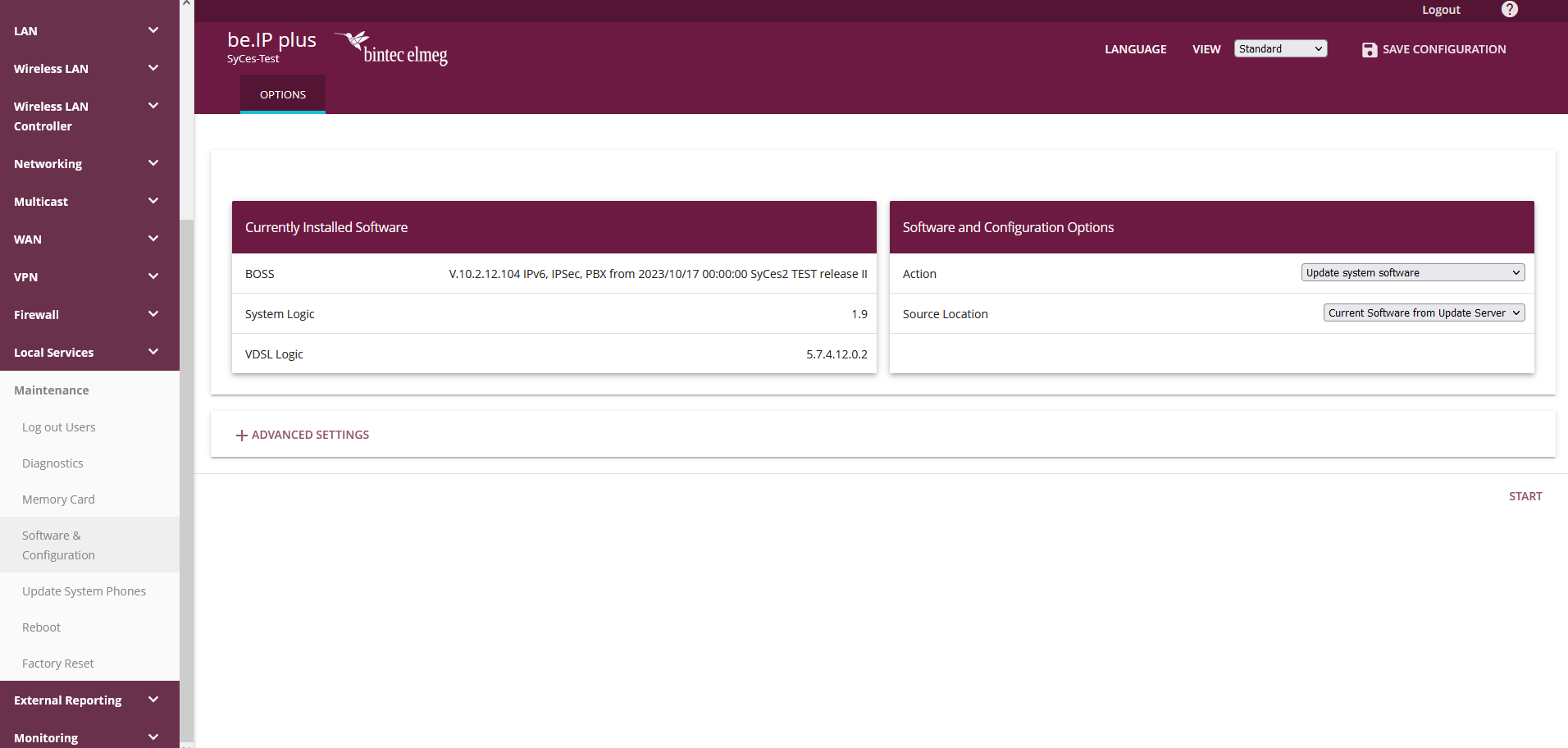
To perform a software update, go to the Maintenance / Software & Configuration tab and select the Update system software action with the source location Current software from update server as shown in the image.
Step 3: Set up network IPs for interfaces
The next step shows the configuration of network IPs for the router's network interfaces.
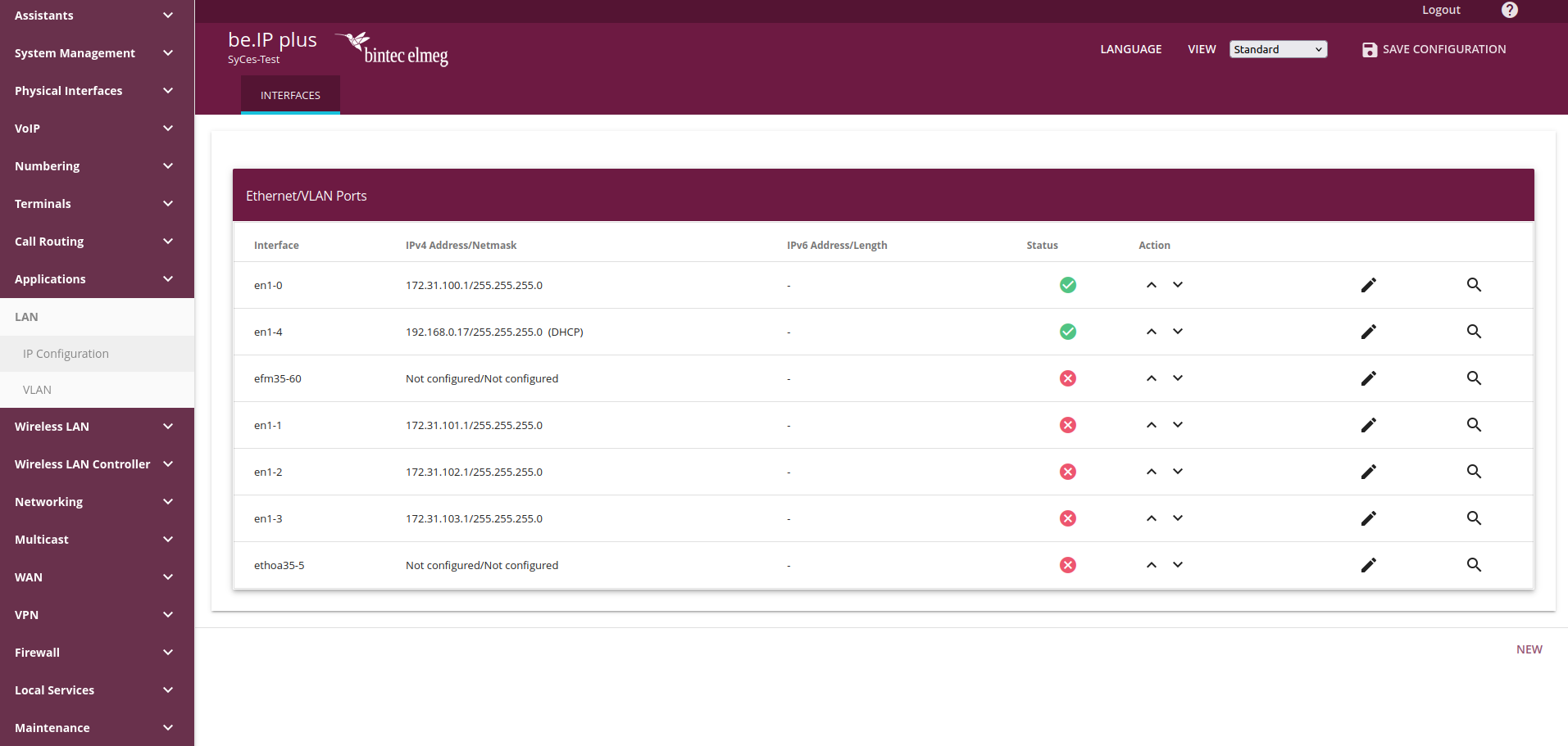
To set up the router's ports open the LAN / IP Configuration manu entry. On this page, the IPs of the router's interfaces can be configured.
To use the router for our hotspot solution, we recommend to configure a WAN port (e.g en1-4), an admin port (e.g en1-0) and a hotspot port (e.g. en1-1).
To edit the settings of an interface, click edit button to the right of the corresponding entry or create a new entry.
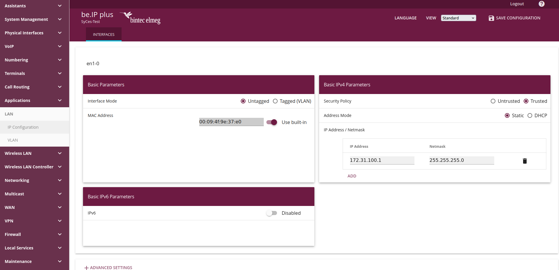
The following explains a configured entry for the WAN port and a local port.
WAN IP configuration
To set up your router's outgoing connection, you can configure the corresponding interface (e.g. en1-4).
In the given example, the router receives an IP address by an upstream DHCP Server, so we set the Address Mode to DHCP.
If this is not be the case for your network, the outgoing network configuration may need to be adjusted accordingly. Information on configuring a static IP address can be found here.
LAN IP configuration
Next, the IP addresses for the router's local networks must be configured. We recommend setting up an administration network (e.g. en1-0) and a hotspot network (e.g. en1-1).
For these local networks, the router should have a static IP and all connecting devices should receive an IP from our router's DHCP server on the configured network. Therefore, the following parameters should be set this time:
- Address Mode:
Static - IP Address: Gateway IP of the network (Convention: IP in local IP ranges
10.x.x.x,172.y.x.x(16 <=y<= 31) or192.168.x.x, ending with.1) - Netmask:
255.255.255.0
Hint: The router's IP in the hotspot network (e.g. 172.31.101.1) must be set either as the Gateway IP of the location in SyCes or behind a local DNS entry (see here).
Also note the router's IP in the admin network for accessing to the GUI (e.g. http://172.31.100.1/).
Validate connectivity
After configuration, ensure that the interfaces are configured correctly. To do this, navigate to the System Management / Status tab. There you will find an overview of the Physical Interfaces. There you can see the configured Interfaces, the assigned IP / netmask and the Link status.
Set up local DNS entry for Gateway IP (optional)
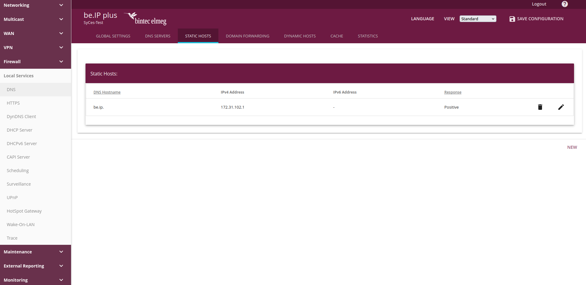
To use a local alias instead of saving the Gateway IP in the location's settings in SyCes, navigate to Local Services / DNS / Static Hosts.
Create or update an entry with:
- DNS Hostname:
be.ip - Response:
Positive - IPv4 Address: IP of your router's hotspot network
In SyCes, navigate to the location's page and enter "be.ip" for the location's Gateway IP. Only IP addresses (in the format x.x.x.x) or the specific keyword "be.ip" can be entered in this field.
This information is required to redirect the authentication request from our self-hosted captive portal to the router in the local hotspot network.
Step 4: Set up the RADIUS server
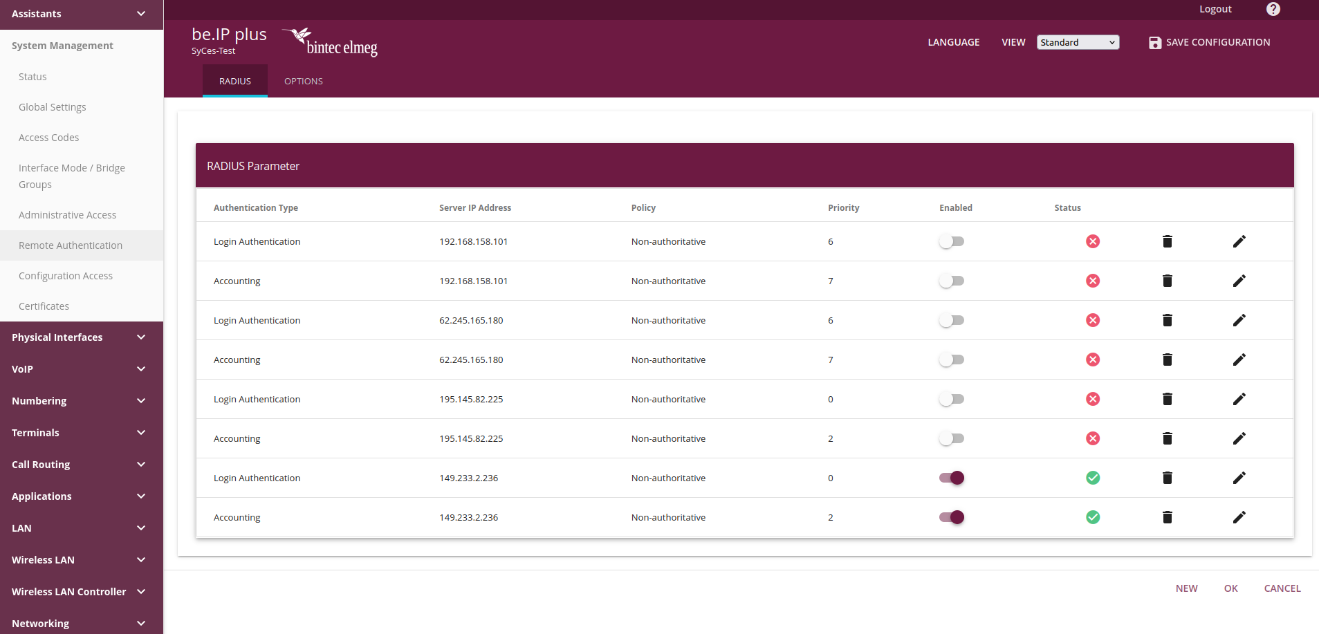
To set up the RADIUS server, navigate to the System Management / Remote Authentication tab.
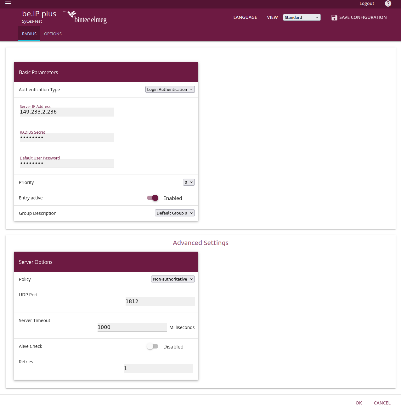
For a basic configuration only the entry for Login Authentication is required.
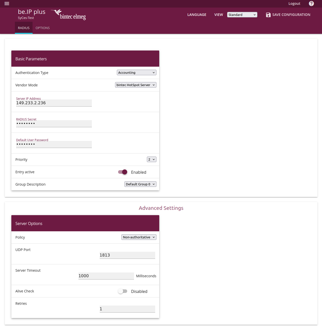
The optional Accounting entry is recommended for logging Wi-Fi data usage and connection time. This setting is required to use SyCes' time- or volume-limited account access.
Hint: When configuring additional entries, ensure that all inactive entries have a different Group Description than Default Group 0. Only active entries should be assigned to this group.
Both entries require the RADIUS server's IP address and secret. These can be found on SyCes. Ensure that the entries are set to Group Description Default Group 0 and that both entries are active.
The Alive Check setting in the Advances Settings deactivates the entry if a connection attempt to the RADIUS Server fails. We recommend deactivating this setting.
After configuration, the entries should look something to this:
For the Accounting entry, the Vendor Mode must be set to Bintec HotSpot Server.
Step 5: Set up hotspot
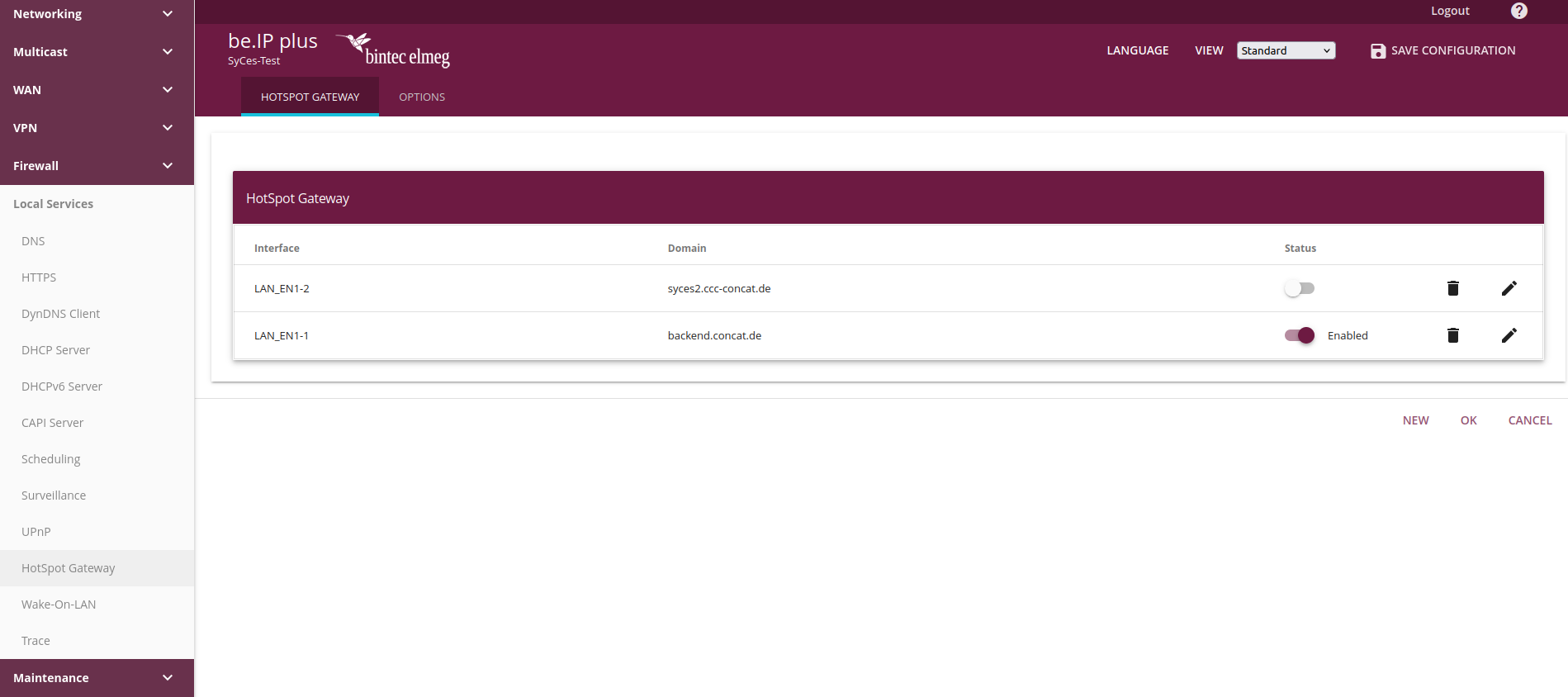
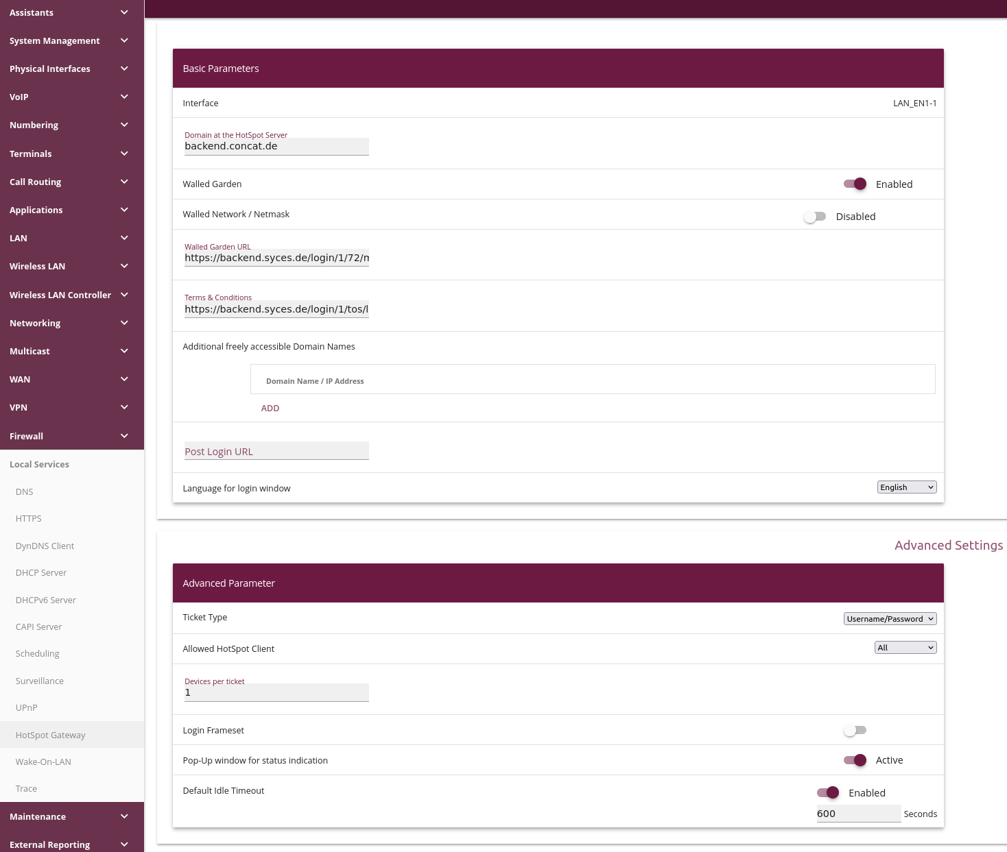
To set up a hotspot, navigate to the Local Services / Hotspot Gateway tab. Here you can edit/create hotspot entries for your interfaces:
To configure a hotspot for accessing the SyCes2 login page, the SyCes domain (backend.syces.de) and a link to the the corresponding location's Walled Garden page in SyCes are required (format https://backend.syces.de/login/<tenant_id>/<location_id>/). This will call the external captive portal, hosted on the Syces servers.
Alternatively, the standard Bintec login mask can be used, if no Walled Garden URL is entered and the Login Frameset field in the advanced settings is enabled.
For basic login functions, specifiying URLs in the Additional freely accessible Domain Names field is not required.
The router address and the specified Walled Garden URL are automatically made accessible to devices before login.
For advanced features (e.g. Facebook or PayPal Login), additional URLs are required. The use of these features might be explained later.
The Terms & Conditions field is not required. A link to the Terms of Service (TOS) page is available on the SyCes2 login page.
This link takes the form https://backend.syces.de/login/<tenant_id>/tos/loc=<location_id>/.
If desired, a Post Login URL can be entered to redirect devices to it after succesful authentication.
If this field is left blank, a connecting device will be shown the standard Bintec page with the current data usage, connection time and a logout button.
Optional URL parameters
To use the Auto login feature of the location in SyCes, the Walled Garden URL can be entered in the format (https://backend.syces.de/login/<tenant_id>/<location_id>/mac=${CLIENT_MAC}/).
This causes the device to call the router with its MAC address as a URL parameter. The server checks whether a device session is active, reauthenticates the device, and logs it in.
Please ensure that the Auto login setting is set to true for the configured location in SyCes.
The language of the walled garden pages is automatically determined by the Accept-Language HTTP request header sent by the client. For most devices, this means that the device's language is used.
If the walled garden page should only be set to a specific language (e.g. German), the parameter lang=de/ can be appended to the link.
If both the MAC address and the language are specified, the MAC address should precede the language:
https://backend.syces.de/login/<tenant_id>/<location_id>/mac=${CLIENT_MAC}/lang=de/
The Terms of Service can also be called with different parameters. The base URL is in the form https://backend.syces.de/login/<tenant_id>/tos/. Optionally, the parameters loc=<location_id>/, mac=${CLIENT_MAC}/, and lang=<language_code>/ (in that order) can be entered:
https://backend.syces.de/login/<tenant_id>/tos/loc=<location_id>/mac=${CLIENT_MAC}/lang=de/
The location parameter loc=<location_id>/ activates a Back to Login link on the Terms of Service page. All available URL parameters are forwarded to the TOS/Login page when using the links on the other page.
Step 6: Login Attempt
After configuring a Bintec router with these settings, connecting a device to the WAP's Wi-Fi should open the website configured for the walled garden. The SyCes2 login page is rendered from the configuration of the location's template configured in SyCes.
The login can be tested by entering valid credentials (existing account or via the self-service portal). After a successful login, the device should display a page with a success message and be logged into the Wi-Fi network.
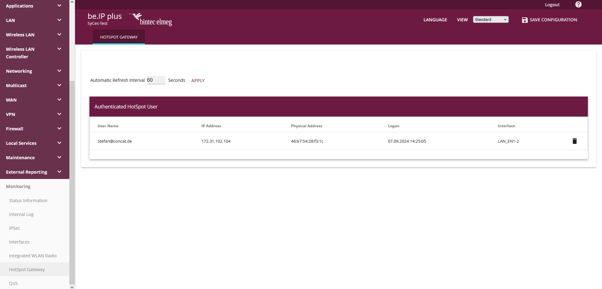
A list of all logged-in devices can be found in the Monitoring / HotSpot Gateway tab of the router settings.
Troubleshooting
If you encounter any problems or unexpected behavior while setting up your router, please contact us at [email protected].
